Search This Blog

Friday, March 30, 2012

Properties Manager


PROPERTIES


LIST  ?    Pft!   ..how old fashioned!  Use the Properties Manager!


The PROPERTIES manager is a wonderful tool. I leave it open all the time.  If you have two monitors, drag it out of your AutoCAD screen and over to another monitor.  Otherwise, leave it open, but collapse it if you want to save some room.


The Properties Manager displays the properties of objects you select, and you can change the properties of those objects as well.  See the image below. I've selected a circle in the drawing and using the properties manager, I can change the layer, color, linetype, etc of the circle. I can also change the location (Center x,y, or z) and the Radius or Diameter.


Properties Manager showing properties of selected circle.


The Properties Manager can also be used for many other things such as to select all your Text and change all that text height or style at once. 


If you select multiple objects like Text, and Circles and Polylines for example, you can check out the properties of each type of object by selecting the Selection Pulldown. Initially it will report "All (7)" (or some other number). 


You can pull down the Selection Pulldown to look at the properties of the "Circles (3)" or "Lines (2)" or "Mtext (2)".


If you suspect you have multiple objects on top of one another, say two identical lines, for instance, you can cross through them and the Properties Manager will report how many items are selected. 


There are also selection tools available next to the Selection Pulldown. The most useful of which is the Quick Select command.  I covered the Quick Select command in my post on Selections.


Be aware of the PickAdd toggle and try not to accidentally turn that on. If you do, you will deselect your first object when you pick a second. You will have to use Shift  to add more objects (like other Windows programs). You can always toggle it off again, of course.

So, if you are still using LIST, try the Properties Manager. Leave it up and open if you have the screen real estate. That way you can just pick on an object and quickly see pretty much anything you would need to know about it as well as have the ability to change the properties you need to change. LIST is still good if you wan to highlight, copy and paste entity information to another document. This is particularly handy with coordinates on civil drawings. 

Bonus Tip: By the way, did you know you can highlight items in the Text Window of AutoCAD (F2), right click and have the option to "Paste to Command Line" ? Handy!

QuickProperties is worth mentioning here. Some find it annoying, but it has merit. You can toggle Quickproperties from the toggle bar shown below.  When you pick on an object or objects, a neutered properties manager pops up to show you some of the more basic properties of the objects selected. You can change the settings of the Quickproperties to display the properties you want to see by right clicking on the side or spine of the QuickProperties box and selecting Customize. 

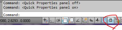
Quick Properties Toggle

That's it for now.  Again, this has been a selection from my AutoCAD Weekly Planner available from the Autodesk Exchange Apps store for $4.  And the text portions are available on Kindle for just $0.99.  Same thing, just no daily planner parts (slots for Monday through Sunday) and no images. 


Later!
Lyle

Wednesday, March 21, 2012

Inventor stuff

I've recently been using Inventor. I've dabbled in it for several years but never really got into it like I have this last week. I've discovered Skeletal Modeling. Holy cow is it fun! I do have to admit that D3 Technologies actually steered me in the right direction by suggesting it.

I had to back up a bit. I am using Inventor 2012 and went to the Help files and took a look at the tutorials. I have to recommend going through the tutorials. They are constructed well and really helped me out. The iLogic tutorials went from easy to advanced really fast, though. I think they need an intermediate iLogic tutorial.

Anyway, I backed up to the basics and did Part Modeling 1 and 2, then Assemblies 1 and 2. From there it was on to Sheet Metal 1 and 2, iLogic, then Skeletal Modeling.

Naturally there are a few good videos on You Tube. Not very much on Skeletal Modeling, though. The ones I found most useful are by Rob Cohee.  Check him out.

The main reason for writing this post is to let you know that the Inventor Tutorials that come with Inventor are definitely worth doing.


Later,
Lyle.


Tuesday, March 20, 2012

Logos for your clients


This blog describes how to create a client logo for the borders of the client’s project.

Logos are an important part of projects and when possible should be included on the drawings issued to the client.  The best way to include the logo is to place it on the border as part of the template file used to create new drawings.

If you need to obtain a logo, this can sometimes be plucked from the client’s web site (right click > Save Image As), from a Google image search, or as a last resort scan a business card.  I prefer the Google image search and try filtering the image size to large.  Make sure it matches the client’s business card to make sure you have the most recent logo. Logos change over the years.

It is best to recreate the logo in AutoCAD because the vector format scales best and usually looks better than an image when printed. Images can look pixilated or generally pretty bad if they are not hi-res images.

Bring the image into AutoCAD. Preferably bring it into a drawing that has a border in it. Place, rotate and scale the image where it should be on the border.  You may temporarily rotate the UCS or even the border and logo if necessary to work with the logo ‘right side up’.

Trace over the logo with AutoCAD lines, polylines, arcs, etc. to recreate the graphic part of the logo.  Hatching can be done with a tight spaced ansi 31. Solid hatching is generally not necessary. Polyline widths other than 0 are not recommended either.  I generally make the current layer an odd color so I can see what I’m drawing over the logo.

For the text portion of the logo, try to use a font that matches as closely as possible to the logo’s font. A good way of doing this is to use Word. Start a Word file and type in the text from the logo. Now highlight that text and run through the fonts in Word to figure out what most closely matches the logo. This might take a while… I’ve found if you pick on the font pulldown in Word, then use your arrow keys, you can scroll down the list pretty quickly. Much quicker that using the pulldown and picking on the fonts one at a time. If you find a good match, make a note of the name of the font and use that font in AutoCAD to create the logo text style. Keep looking though because there might be an even better match. If you cannot find a good match, you may have to carefully trace over the text in AutoCAD with lines and arcs.

Once you have the text in AutoCAD, (you will have to explode it if it is Mtext) you will need to adjust height and width with the properties manager to get the AutoCAD text to match the logo text. You may need to edit the style to fiddle around with the oblique angle as well. Try to get it to match perfectly. Companies spend a lot of money creating their logos. Respect that and try to get your logo to match theirs as close as possible. It would be a slap in their face if you made a crappy looking logo for them.

Once the text is done and looks good use TextExplode from the Express tools to explode it into polylines. This prevents the text from changing if someone should redefine the text style or if a font is missing from someone’s machine.

Here’s a neat trick. You’ll find that textexploding the text creates all sorts of lines you may not want. Here’s what you do. Type REGION and select all the polylines that were created from exploding the text. Now type UNION and select all the new regions. You now have better looking text shaped polygons, but they are still regions. If you want them as polylines so you van further edit them, draw a single rectangle around the all the regions and use the BOUNDARY command to create polylines around the regions. Erase all the regions. (Use QUICKSELECT to filter out and select all the regions). Now you can edit and hatch the polylines if necessary.

Create Layers called T-xxx-LOGO-yyy  where xxx is the client name and yyy is the logo description such as color or text.  Make the layers the appropriate colors and change the logo entities to the appropriate layers.  The naming is clearly optional for your purposes, but you probably don’t want the logo entities to be on the layer C-DIMS or something.

Finally, once all is created, scaled, and colored, you can restore the World UCS and/or rotate your logo and border back to where they should be. Detach the image. Erase the border. Set the current layer to 0 and purge audit purge the drawing.

Save the logo as XXX-LOGO where XXX is the Client name. Again, name it whatever you like. Save the logo in a general location where you can find it later. We sometimes Xref the logos in case there is a change midway through the project. We also keep all our logos (and other general blocks) in a place called P:\acad\blocks\general.

I know a lot of this was just common sense, but I hope this has been somewhat helpful in some way.

‘til next time,

Lyle.


Tuesday, March 6, 2012

'ZOOM and other Transparent Commands

ZOOM! and Transparent Commands

Zoom? Really? What's to know? Well, there's more to ZOOM than meets the eye. 


ZOOM


Yes, one of the oldest commands, but there are some neat things you can do with it.

First of all, Zoom Window, can be faster than using the mouse wheel especially in large drawings. Actually, while on that topic, I'm surprised how many people don't use the mouse wheel to zoom. But, using the mouse wheel is for another post....

To save a step when zooming a window, you don't need to type in W for window, Window is the default. Just Z for zoom (or 'Z for a transparent zoom. See below.) and pick your two window corners. The 'Z will issue a transparent Zoom. That is, it can be issued during another command, such as in the middle of Move or Erase. The quote mark ( ' ) will cause some commands to be transparent such as 'ZOOM and 'PAN among others. More on that below.

Look at the command line after issuing the Zoom command and experiment with the Zoom options.

Here's a tip: 
Zoom Object Last. ( Z enter, O enter, L enter). This will zoom to the last thing you drew or placed in the drawing. This works with the Previous (P) selection set, too. Z enter O enter P enter.

Zoom Object Last is my favorite way to find where, in modelspace, a viewport is viewing. Did you follow that? You know in some big drawings, you get 'lost' when going from a viewport in paperspace to modelspace?
Here's how to find out where you are: 

Through the viewport, draw a circle (or anything really. I just like circles). Go to the Model tab and Zoom, Object, Last ( Z Enter, O Enter, L Enter ) and it will zoom to that circle. This tip is great for large site plans or confusing drawings with a gazillion viewports showing a gazillion details. Sometimes, you're not looking where you think you are.

Quickly Zoom Extents by double clicking the Mouse Wheel (or middle button).


Zoom Dynamic has been all but forgotten by most. It allows you to create a temporary window that you can size and move around your drawing to zoom into a specific area. Again, it's probably quicker to Zoom Extents, then Zoom Window or to just use the wheel, but some people still like to zoom dynamic.


Zoom Center centers the screen where you pick, but you also get to enter a scale or height to zoom to. In all honesty, I can't really think of much value to that other than zooming to a point in a LISP routine or a script or something. 


Again, just type Zoom and experiment with the various options. You might find something you like.
The system variable ZOOMFACTOR controls how much you zoom in and out with each 'click' of
the mouse wheel.


COMMAND LINE AND TRANSPARENT COMMANDS

If you've used AutoCAD for many years, you may remember when it was all Command line driven (back in the days of DOS for instance). There were few dialog boxes back then.
TRANSPARENT commands are those commands you can use while in the middle of another command. The most useful and well known are 'ZOOM and 'PAN. Notice the single quote mark ( ' ) before the command. That is what is needed to make the command transparent. 'LAYER is another command you can use transparently. The usefulness of Transparent commands has diminished with the use of mouse wheels (ZOOM & PAN) and dialog boxes (LAYER), but can still be useful at times. To see if a command has a command line equivalent or might be transparent, just type - or ' before the command to see it is a valid command or not.
Many commands still offer command line versions by using a dash (-) before the command. For instance, type "-LAYER" (without the quotes, but with the dash) and you will get the old fashioned command line version of the LAYER command.


A few other commands are -PURGE, -BLOCK, -WBLOCK, -SAVEAS, etc. This is useful to know for writing scripts, macros and LISP routines. Note that not all commands have command line equivalents.


Well, that's it for another week. 
Live long and prosper.
Lyle